Dreamcast 32MB RAM upgrade

This article describes how to upgrade a Dreamcast from 16MB to 32MB of system SDRAM. I have done this exactly once, so this is still rather experimental. Please only attempt this with a spare Dreamcast you don’t mind destroying.
I’d love to hear from you if you have been able to reproduce this, and I’m happy to help troubleshoot. Good luck!
- Theory
- 512K x 32-bit x 4 SDRAMs
- 1M x 32-bit x 4 SDRAMs
- 2M x 32-bit x 4 SDRAMs
- Process
- Requirements
- Materials
- Tools
- Skills
- Overview
- Step-by-step instructions
- 1. Remove the original SDRAMs
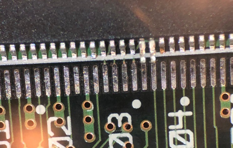
- 2. Bend up pins 21 and 22 on the new SDRAMs
- 3. Solder the SDRAMs to the motherboard
- 4. Solder a wire from pin 86 (VSS) to pin 21 (A11) on both SDRAMs
- 5. Reassemble the Dreamcast and verify that it still works
- 6. Flash an AMX 3 Dreamcast BIOS
- 7. Remove the motherboard again and remove the wires you added in step 4
- 8. Remap pins 22 and 23 on each SDRAM
- 9. Assemble the Dreamcast and boot the AMX 3 BIOS you flashed in step 6
- Requirements
- Software
- Existing library
- KallistiOS
- ScummVM
- Discussion
Theory
There are 13 address pins (A15-A3) connected between the Dreamcast’s SH-4 CPU and its SDRAM. Two, A15 and A14, are used to select the SDRAM bank address. The row and column addresses are multiplexed on the other 11 pins.
Years ago there was a discussion on ASSEMbler Games (https://www.assembler-games.com/threads/sega-dreamcast-system-ram-16mb-jtag-hack.41785) about how to access additional address pins on the SH-4 so that more memory can be addressed. Unfortunately, the A16 address pin is not connected, and it also happens to be on an interior row of a BGA chip, so the only ways to access it would be by drilling into the PCB from the back or by removing the chip and reflowing it back on with a wire attached to the A16 ball. I’m not sure if anyone has succeeded with that yet.
But reading that thread got me thinking about how memory addresses are multiplexed on the SH-4 bus, and it turns out that it’s possible to address more memory by changing how the existing address bus is utilized.
Let’s look at some of the SDRAM address multiplexing options available.
512K x 32-bit x 4 SDRAMs
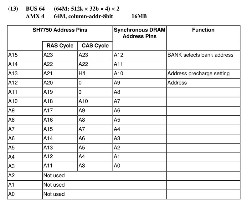
The Dreamcast comes with two 512K x 32-bit x 4 SDRAMs for a total of 16MB.
64-bit data (32 bits from each SDRAM) is addressed by 11-bit row addresses and 8-bit column addresses. The SH-4’s address multiplexing is controlled by the AMX2-AMX0 pins of the MCR (see Section 13 (Bus State Controller (BSC)) of the SH7750 Hardware Manual for more details). The Dreamcast BIOS sets AMX very early in the boot process, before it copies itself to SDRAM. An unmodified Dreamcast uses AMX 4.
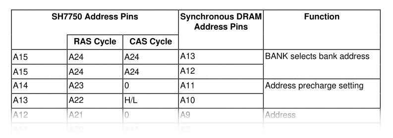
Here’s how AMX 4 works (from Appendix F of the SH-7550 manual):
(A12 and A11 on the SDRAM are BA1 and BA0, respectively)
1M x 32-bit x 4 SDRAMs
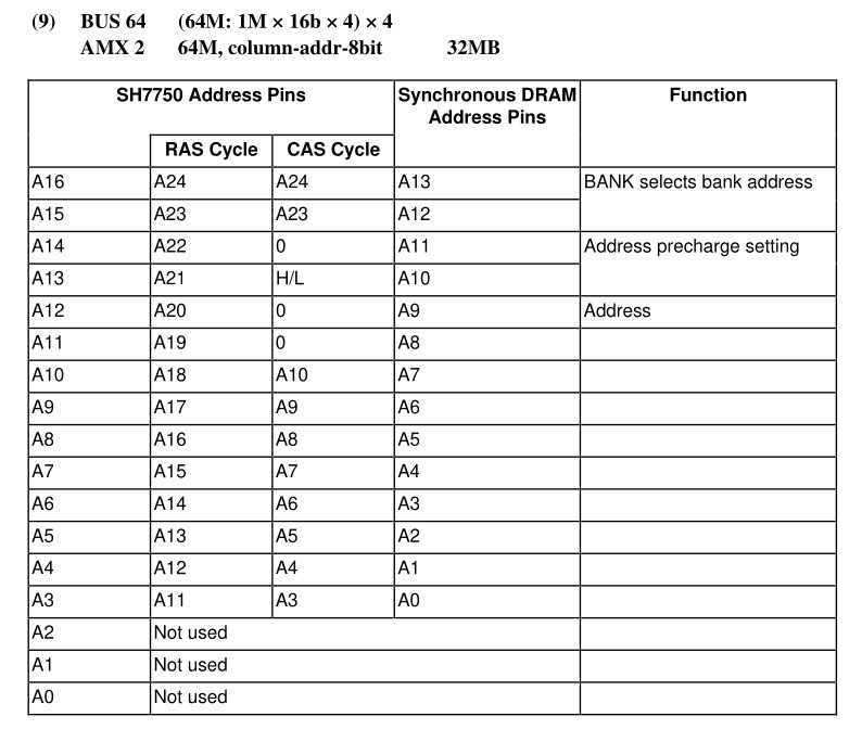
The ASSEMbler Games thread considers replacing those with 1M x 32-bit x 4 SDRAMs for a total of 32MB. These SDRAMs have an additional address pin (A11) and use 12-bit row address and 8-bit column addresses. Setting the 12th row address bit would require connecting the SH-4’s A16 which is not easily accessible, but here’s how the address multiplexing would look:
2M x 32-bit x 4 SDRAMs
Another approach is to use 2M x 32-bit x 4 SDRAMs because they have 12-bit row addresses and 9-bit column addresses. The SH-4 can still only drive 11 bits of the row address, so it can only address half of the available 64MB of RAM, but it can still use the extra column address bit to address 32MB.
One nice property of these SDRAMs is that if you tie the A11 pin to ground, they behave exactly like the original 512K x 32-bit x 4 SDRAMs and can be used with an original AMX 4 BIOS. Only 16MB can be addressed in this configuration, but it provides a way to verify that the SDRAMs are working after you install them but before you rewire them and switch to an AMX 3 BIOS so that 32MB can be addressed.
Here’s AMX 3, the address multiplexing mode for 2M x 32-bit x 4 SDRAMs:
(A13 and A12 on the SDRAM are BA1 and BA0 now)
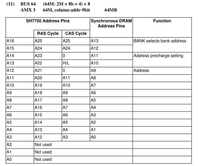
The Dreamcast is still wired for AMX 4, so the above is not actually how things are connected. In reality, the SH-4’s A16 is unconnected, the SH-4’s A15 is connected to the SDRAM’s A13/BA1, and the SH-4’s A14 is connected to the SDRAM’s A12/BA0, like this:
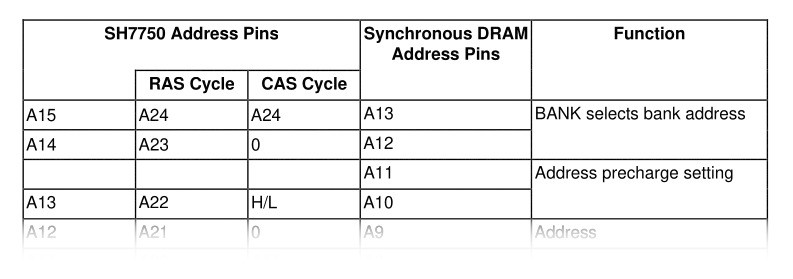
That configuration won’t work because the SH-4 will change the bank address during the CAS cycle by pulling the SH-4’s A14 low.
But it will work if you tie the SDRAM’s A12/BA0 and the SDRAM’s A13/BA1 together (so that both are driven by the SH-4’s A15) and attach the SH-4’s A14 to the SDRAM’s A11:
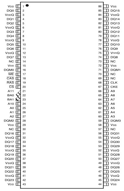
To achieve this in practice, you just need to scoot a couple of pins over: bend pin 22 and solder it to pad 23, then bend pin 21 and solder it to pad 22, like this:
(Pins 22 and 23 are both soldered to pad 23. Pin 21 is the only pin soldered to pad 22.)
The BIOS needs to be modified to use AMX 3 in order to use the SDRAMs in this configuration.
Process
Requirements
Materials
- A Dreamcast modded with a writable BIOS. I used a VA1 and haven’t tested other revisions.
- Two pin-compatible 86-pin TSOP2 (2M x 32-bit x 4) SDRAMs with 9-bit column addressing. I used two IS42S32800J-6TL SDRAMs, but I don’t see a reason why the slower -7 and -75 speed grades wouldn’t work as well.
- ~30 AWG wire (optional but recommended).
Tools
- A hot air rework station
- A soldering iron, flux, flux cleaner, solder wick
- Tweezers and pliers for lifting and straightening IC pins
- A multimeter for checking for shorts
Skills
- Disassembling and reassembling Dreamcasts
- Using hot air to remove surface mount ICs from a PCB
- Soldering surface mount (0.8mm pitch) ICs
- Patching binaries using a hex editor
- Flashing BIOS images using Dreamshell
Overview
I recommend installing the new SDRAMs in AMX 4 mode so that you can test them with an original BIOS before rewiring them for AMX 3. In my case this paid off because at first, my Dreamcast didn’t boot with the new SDRAMs in AMX 4 mode, and I had to go back and touch up the soldering to get it to work.
If you are more confident in your rework/soldering skills, steps 4, 5, and 7 are optional if you do step 6 ahead of time.
- Remove the motherboard and use a hot air station to remove the original SDRAM chips.
- Bend up pins 21 and 22 on both SDRAMs.
- Solder the new SDRAMs to the motherboard. For each SDRAM, bend pin 22 down enough so that you can solder it to pad 22. Leave pin 21 lifted and disconnected.
- Solder a wire from pin 86 (VSS) to pin 21 (A11) on each SDRAM.
- Assemble the Dreamcast and power it on with an original BIOS (AMX 4). If everything went well, it should boot normally.
- Flash the BIOS with a modified BIOS that sets AMX 3. You will not be able to boot this BIOS until the SDRAMs have been rewired in step 8.
- Remove the motherboard again and desolder the wires between pins 86 and 21.
- Lift pin 22 and solder it to pad 23, and lift pin 21 and solder it to pad 22.
- Assemble the Dreamcast again and boot the modified (AMX 3) BIOS. It should boot normally. The AMX 4 BIOS will no longer work.
Step-by-step instructions
1. Remove the original SDRAMs
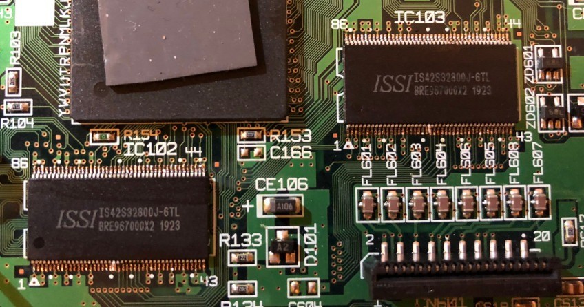
Disassemble the Dreamcast and remove the motherboard. Identify the system SDRAM chips (IC102 and IC103). Your SDRAMs may have different a different part number and manufacturer as several different parts were used.
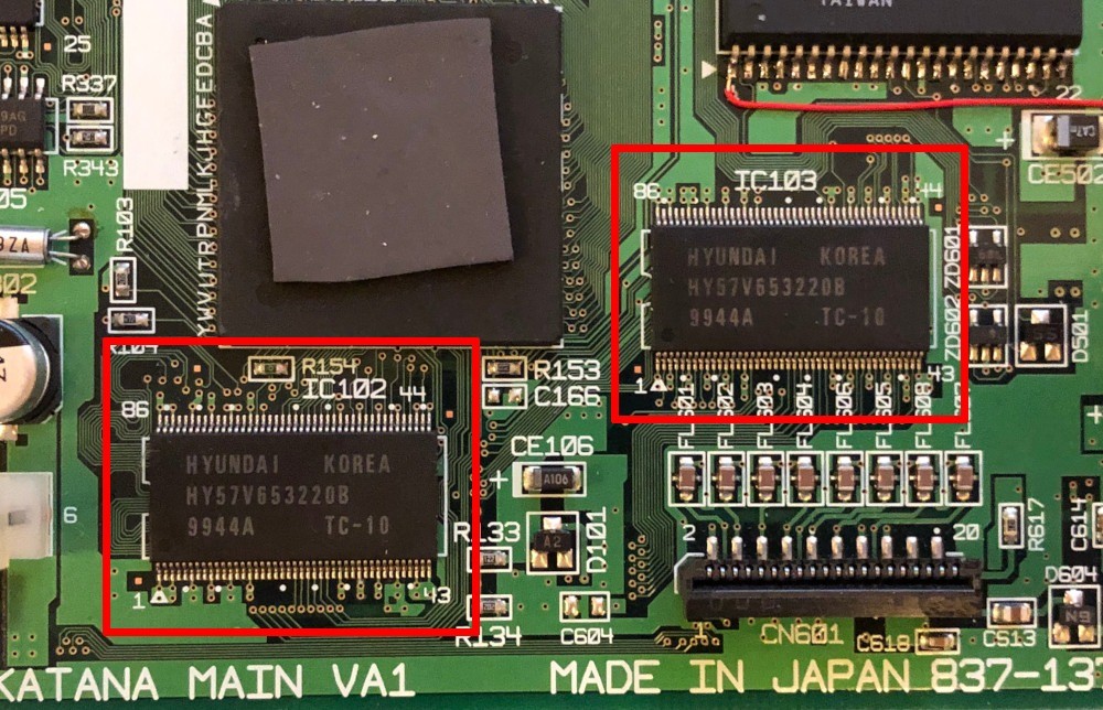
Use a hot air station to remove the original SDRAMs and clean up the pads with solder wick and flux cleaner.
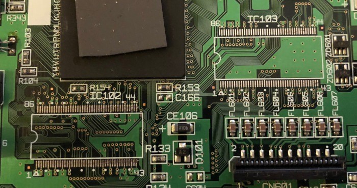
2. Bend up pins 21 and 22 on the new SDRAMs
I prefer to lift and straighten the pins at this point before the chips are soldered down.
You can use the motherboard silkscreen as a guide to identify the pins. The silkscreen marks every 5th pad with a white dot. Line up the SDRAMs with the IC103 pads:
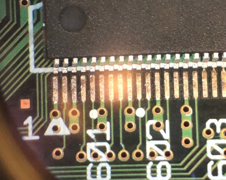
Use the white dots to identify pins 21 and 22:
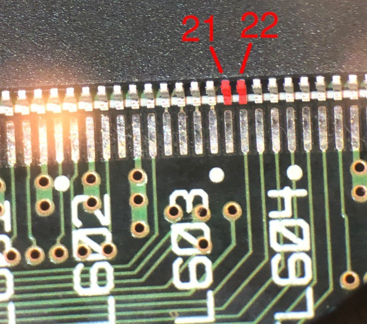
Then bend both of them up with tweezers so they are at a 90 degree angle from the rest of the pins and straighten them with pliers:
3. Solder the SDRAMs to the motherboard
On each SDRAM, leave pin 21 (the left lifted pin) unconnected, but bend pin 22 (the right lifted pin) back down enough so that you can solder it to pad 22. You will lift it up again in step 8.
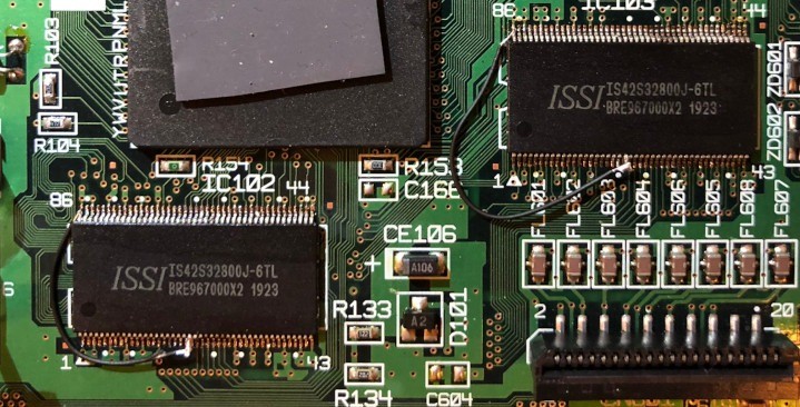
4. Solder a wire from pin 86 (VSS) to pin 21 (A11) on both SDRAMs
This is temporary, so it doesn’t have to be pretty.
5. Reassemble the Dreamcast and verify that it still works
At this point only 16MB will be available, but this will verify that the SDRAMs have been installed properly. You should be able to use the BIOS menu, run a program from a disc, etc.
6. Flash an AMX 3 Dreamcast BIOS
EDIT: darc has created a Dreamshell image with 32MB-patched versions of many BIOS images (https://dreamcast.wiki/32MB_RAM_expansion)
I modified v1.032 of japanese-cakes’ excellent Custom BootROM (SHA1 ec42875983f33cefafe8616eb9152cf0172136ae) (https://blog.japanese-cake.io/index.php/2016/06/20/release-custom-bootrom-v1-032/) to use AMX 3.
The two values this BIOS uses to load the MCR are stored at addresses 0x005074 and 0x005078. To modify the BIOS to use AMX 3 instead of AMX 4, use a hex editor change these two bytes from 0x24:
00005070: 1101 1101 240e 0a80 240e 0ac0 9001 94ff  ....$...$.......
                    ^^        ^^
To 0x1c:
00005070: 1101 1101 1c0e 0a80 1c0e 0ac0 9001 94ff  ....$...$.......
                    ^^        ^^
The end result, an AMX 3 BIOS, should have SHA1 sum cf64d6509aadde812500db0f7571fd51e0ff85bb.
Use Dreamshell to flash the AMX 3 BIOS. You won’t be able to boot from the AMX 3 BIOS just yet.
7. Remove the motherboard again and remove the wires you added in step 4
Don’t skip over this step just because I don’t have anything more to say about it.
8. Remap pins 22 and 23 on each SDRAM
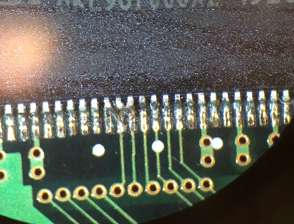
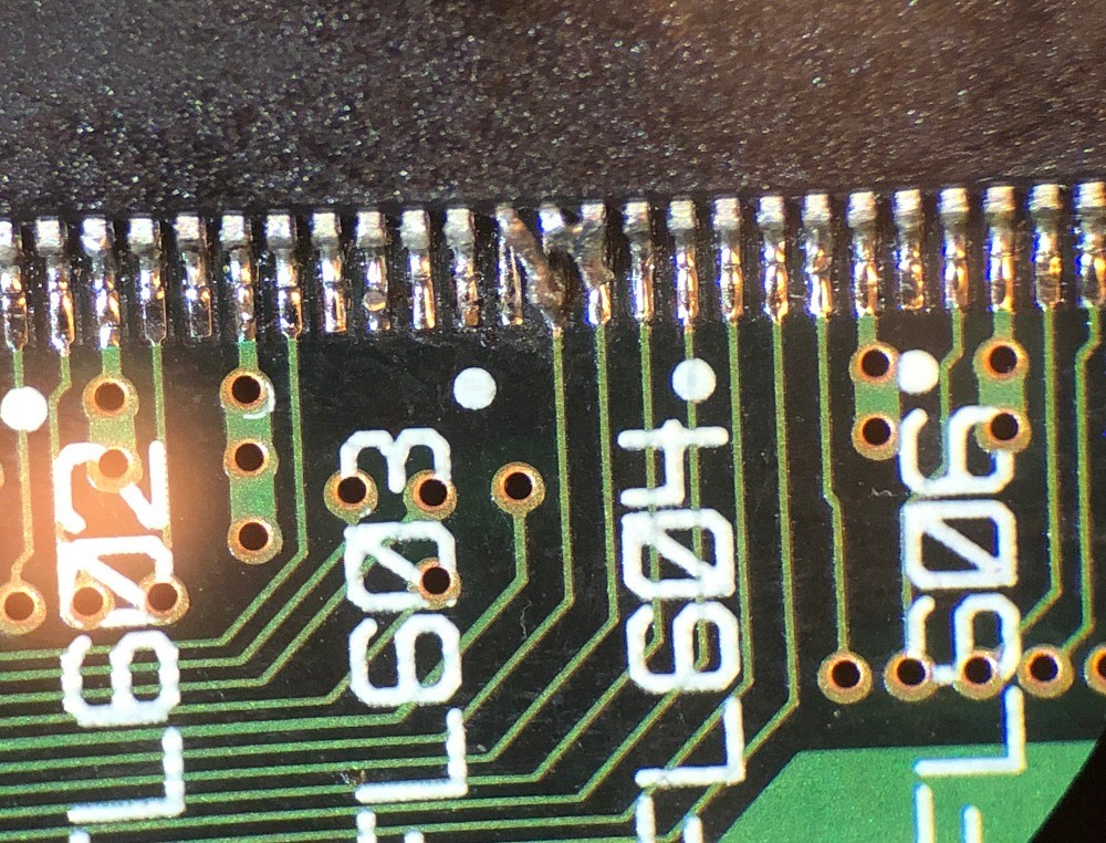
On each SDRAM, lift pin 22, bend it to the right so that it touches pin 23, and solder it to pin 23. Also on each SDRAM, bend pin 21 to the right and solder it to pad 22.
The result should be that pins 22 and 23 are soldered together, and pin 21 should be the only pin soldered to pad 22.
Here’s the finished IC102:
The finished IC103:
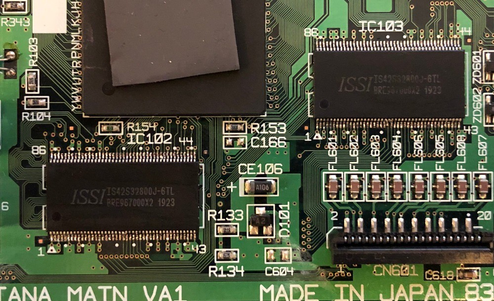
And a bird’s eye view of the finished product. It’s difficult to see the remapped pins from this distance.
9. Assemble the Dreamcast and boot the AMX 3 BIOS you flashed in step 6
The AMX 4 BIOS will no longer run, but the new AMX 3 BIOS you flashed in step 6 will work now.
Software
Most software will need to be modified to take advantage of the extra RAM. It should be possible for software to check the MCR at runtime to determine how much RAM is present, but I’m not aware of anything that does that at the moment. I’ve only tested with KallistiOS using the changes described below.
Existing library
EDIT: It appears that some retail Dreamcast games (based on a not-so-random sampling, about 25% of them) are not compatible with this mod. I’m not yet sure why they don’t work or what can be done to make them work.
KallistiOS
You should just need to replace 0x8d000000 (the 16MB ceiling) with 0x8e000000 (the 32MB ceiling) throughout the KallistiOS source. Here’s a patch against commit c989f25 (https://blog.ldtlb.com/assets/posts/dreamcast-32mb-ram-upgrade/KallistiOS-32mb.patch) that does that.
Note that some of these changes are for patches that KallistiOS applies to gcc that determine where the stack is placed. You will need to recompile your KOS toolchain after applying the above patch so that the stack gets placed at the new ceiling. If the stack still starts at 0x8d000000 you will probably have a bad time trying to extend the heap into the upper 16MB of SDRAM.
EDIT: See here (https://github.com/tsowell/KallistiOS-scummvm/commit/09aea2bb3becc22dc4f178cf4200164659177c76) for an example of adding runtime 32MB support to KallistiOS.
ScummVM
EDIT: In the latest release (https://github.com/tsowell/scummvm-dreamcast/releases) my alternate ScummVM backend for Dreamcast (https://github.com/tsowell/scummvm-dreamcast/blob/dcalt-backend/backends/platform/dcalt/README.md) now supports both 16MB and 32MB Dreamcasts from the same binaries. ScummVM supports several games that run well on Dreamcast but require more than 16MB RAM.
original article: https://blog.ldtlb.com/2020/06/21/dreamcast-32mb-ram-upgrade.html


