G1-ATA (IDE) adapter

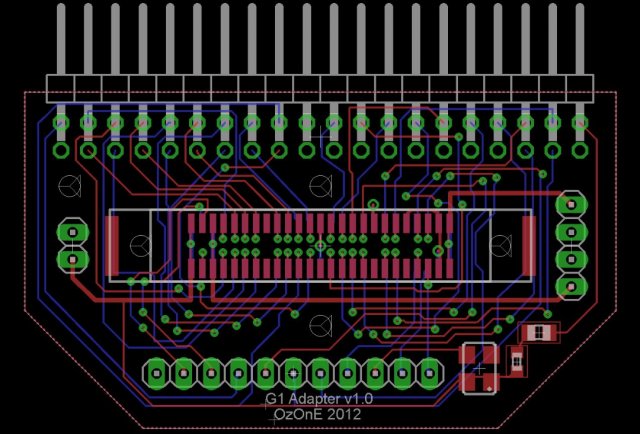
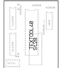
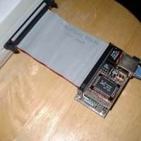
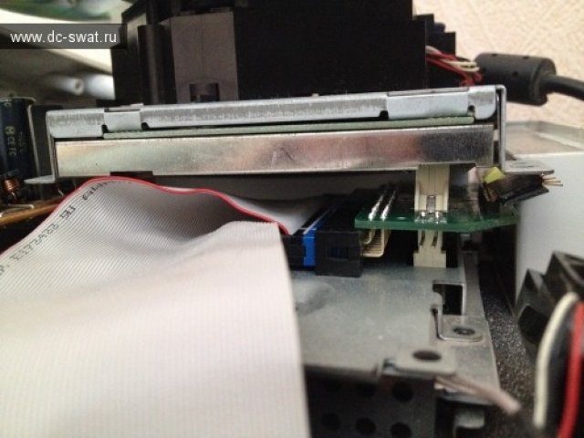
This is a first version of G1-ATA adapter.
The printed circuit board is provided with small errors in size, so if you can draw yourself, do it better.
Or you can wait the new version of PCB from OzOnE.
And of course you can solder wires directly to the motherboard.
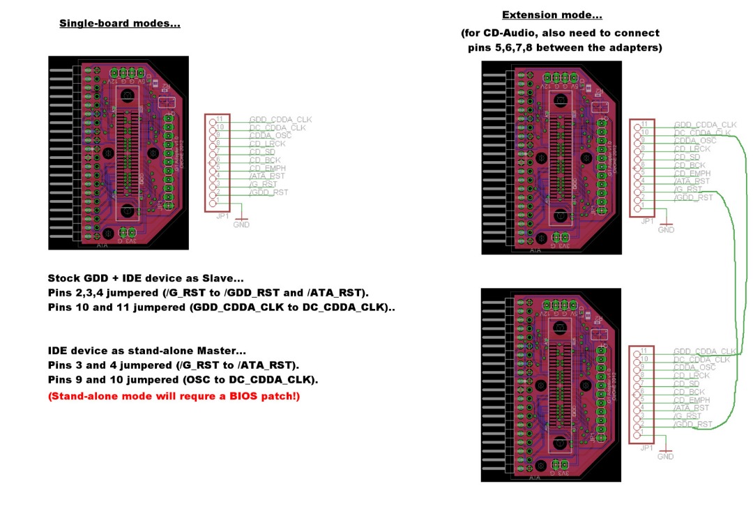
You can use IDE HDD (need external power) or CompactFlash cards (powered from DC).
Maybe some adapters IDE->SATA/SD etc will work too, but this is not guaranteed.
Prepare in advance for release DreamShell 4.0 RC 2 ;-)
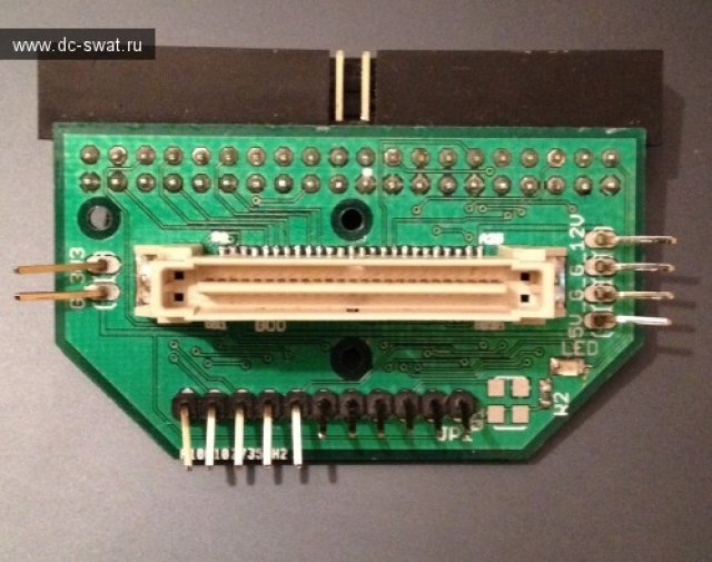
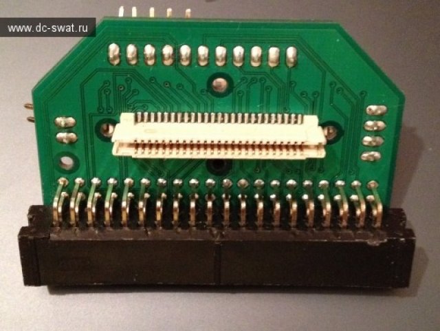
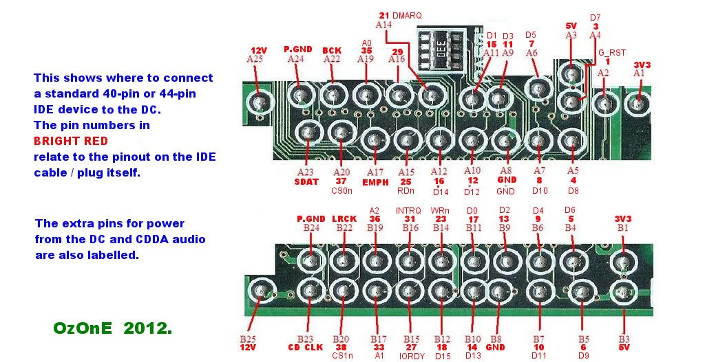
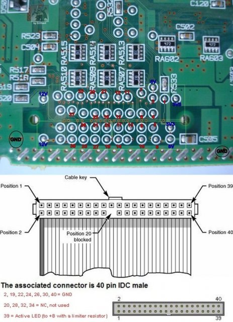
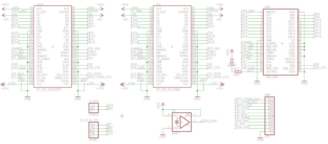
IDE/ATA... DC G1 port...
1. /RESET A2
2. GND A8
3. DD7 A4
4. DD8 A5
5. DD6 B4
6. DD9 B5
7. DD5 A6
8. DD10 A7
9. DD4 B6
10. DD11 B7
11. DD3 A9
12. DD12 A10
13. DD2 B9
14. DD13 B10
15. DD1 A11
16. DD14 A12
17. DD0 B11
18. DD15 B12
19. GND B8
20. Key (NC)
21. DMARQ A14
22. GND A13
23. /WR B14
24. GND B13
25. /RD A15
26. GND A18
27. IORDY B15
28. CSEL (NC)
29. /DMACK A16
30. GND B18
31. INTRQ B16
32. /IOCS16 (NC)
33. DA1 B17
34. /PDIAG (NC)
35. DA0 A19
36. DA2 B19
37. /CS0 A20
38. /CS1 B20
39. /DASP (/ACTIVE LED)
40. GND A21/B21
DC G1 port POWER...
A1/B1 = 3V3
A3/B3 = 5V
A25/B25 = 12V
A24,B24 = P.GND (Power Ground)
A8,B8,A13,B13,A18,B18,A21,B21 = GND
DC G1 port CDDA pins...
A17 = CD_EMPH (Emphasis)
A22 = CD_BCK (Bit Clock)
A23 = CD_SD (Serial Data)
B22 = CD_LRCK (Left / Right Clock)
B23 = CDDA_CLK (33.8688MHz master clock INTO AICA!)
