VMU External Power Mod
This is a step by step guide to help you use your VMU without the use of those CR-2032 batteries that cost a fortune for most people. Note, NO SOLDER REQUIRED.

All the guides I ever found had these mods where you had to have a dremel, Sub-D 25-pin connectors, adhesive tape or solder 100 wires! Screw that, I don't have that much time and want to do this to all my VMU's, so...
This is the birth of this guide.
Materials:
1. Razor knife or equivalent.
2. Wire (nothing too thick like 22-20 AWG).
3. Two Ring Terminal wire connectors (red is best).
4. A connector (Like an RCA male and female, two Disconnect Spade Terminals, or other...).
5. Wire Strippers (use a knife if you don't have these).
6. Pliers (if you do not have strippers)
7. 6-Volt Power Adapter or a battery pack.
8. A thin phillips screwdriver or "tweeker".
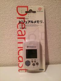
9. The star of this production the Dreamcast VMU (lol).

Operation:
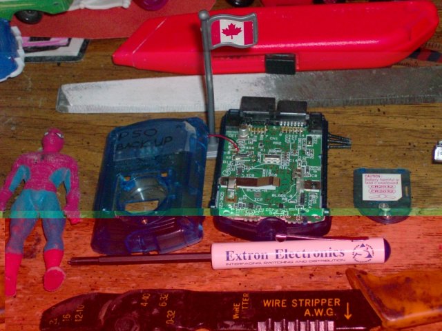
1. Open the patient (VMU) by removing the batteries (forever) and four corner screws.
2. Prep the wires by stripping the ends and then twist them. The wire should start out at about 13mm (5 inches). The wire I used has a trace (a coloured stripe) on one of the two leads. Coloured wire is also a good idea.
3. Ok, now you need to crimp one end of the wire only with the Ring Terminal connector (pictured below).


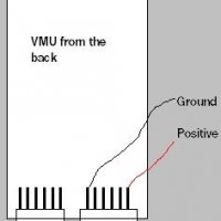
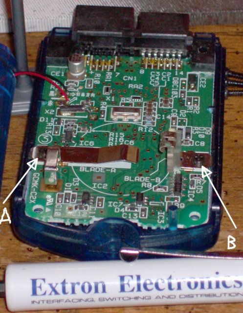
4. Connect them to to the VMU circuit board at the "Blade A" and "Blade B" as indicated below:
a. Connect trace wire (or colour of your choice) to "Blade A" (positive polarity).
b. Solid colour wire (or "other" colour of your choice) to "Blade B" (negative polarity).
Please note the colour of the wire you're using because the polarity will be an issue later. Also, be sure to not screw too tight, or you'll strip out the screw holes.

5. Notch out the inner bottom housing with a knife (indicated below). The notch out should be at the semi-circle. Be very careful not to put stress on the two speaker wires.
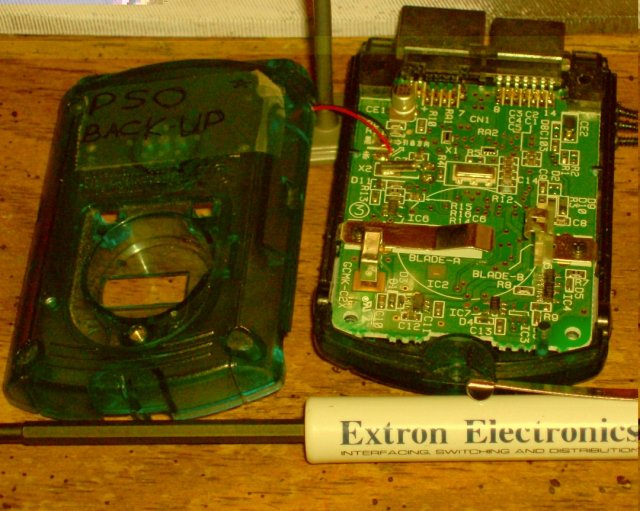

6. Now, route the wires around the battery housing and thru the notched section of the VMU.
7. Close up the patient.
8. Now, all you need to do is connect your power source (4 1.5-Volt batteries or 6-Volt power supply). This end of the wiring is up to you to connect. I used male/female disconnect spades, the trace (or coloured) is the negative.
Once connected, turn it onFire it up and you have a working off-line VMU. Now, back to the VMU Super Bowl where I have the Pittsburgh Steelers and Impulse is the Arizona Cardinals...lol!
(Yes, Impulse is actually a Steelers' fan)